Elevator robot
Designing the sensor network
One of the problems in building an elevator using an rcx as controller, is the lack of sensors. We need three sets of sensors: floor detect, cabin call, destination select.
Floor detect Firstly, we need to detect on what floor the elevator cabin is. With some trickery, a single touch sensor could work. For example, we could attach the touch sensor to the cabin, and have notches in the shaft at the floors. If we would first drop the elevator (using a motor with a slipping belt) until the touch sensor would no longer release, we would know the cabin is at the lowest floor. However, out of simplicity we could also have one button per floor (if only we had enough sensors and sensor ports... read-on!)
Cabin call Secondly, at each floor we want a button that allows us to call the elevator to that floor. Since we want actual buttons, we really need one per floor.
Destination select Finally, in the cabin, we want a button per floor, to send the cabin to that floor. It should be noted that the "cabin call" buttons are actually equal to the "destination select" buttons: one button per floor, to send the cabin to that floor. The only difference is the location of the buttons: one per floor (cabin call) or neatly organized inside the cabin (destination select).
Out of sense of uniformity we decided that for each of the functions we would reserve a button per floor, and we would multiplex them to a single rcx input port. The table below gives an overview; we see that we need 9 touch sensors (I bought them via BrickLink).
|
Multiplexing 3 touch sensors to a single port is relatively simple. See for example Techno stuff. The trick is that in raw sensor mode, the rcx does a 10 bit ADC measurement with a 5V reference voltage and a 10k pull-up resistor (I learned that from Claude Baumann). What does this mean? See the schematic below.
The equivalent schematics of a raw sensor
Calculus and Ohms law, now tell us that the current total resistance equals 10kΩ+R, so that the current I equals 5V/(10kΩ+R). This means that the voltage measured by the ADC equals (5V×R)/(10kΩ+R) or 5R/(10k+R). The raw read-out is scaled to 10bits (a factor 1023/5), so that it equals 1023R/(10k+R) The following table shows these computed values. It also shows measured values obtained by connecting actual resistors to the rcx and checking the rcx display in 'view' mode.
|
The touch sensor multiplexer of Techno Stuff is a resistor network. It has with 3 parallel resistors that may be added or not depending on the state of the touch sensor connected to inputs of the mutiplexer (sub1, sub2, sub3 in the diagram below).
The schematics of the Techno Stuff multiplexer
The Techno stuff multiplexer uses resistors of 62k, 30k and 15k. Assuming an internal resistor of 1k in the touch sensors, we would end up with the 8 situations of the table below.
|
Manufacturing the sensor multiplexer
We follow the design of Techno Stuff and the way of working of ABS-Robotics. See the diagrams below.
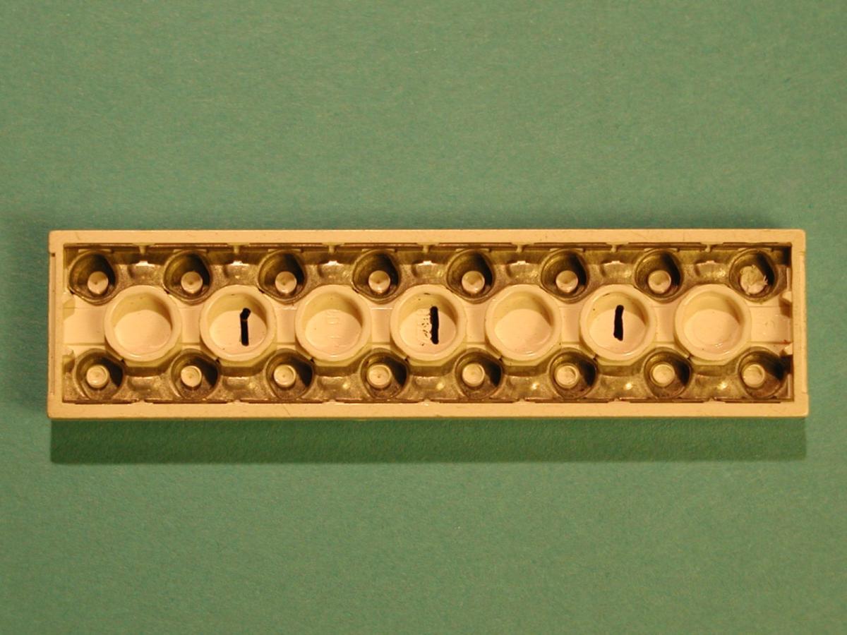 Step 1: Putting marks on the inside of an electric plate to divide it in 4 parts |
 Step 2: Using a small drill-bit to manually scrape away the melted plastic "welds" of the top strip. |
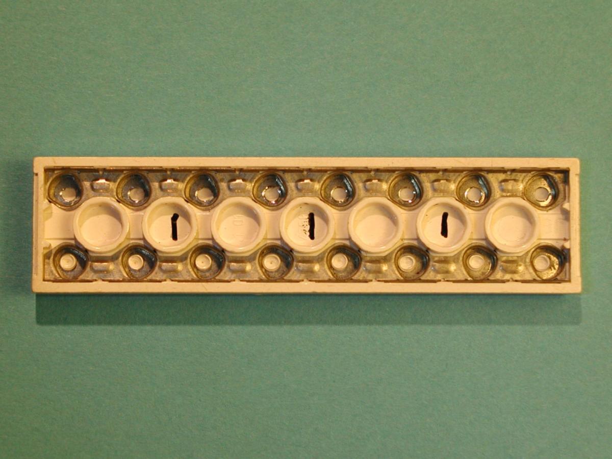
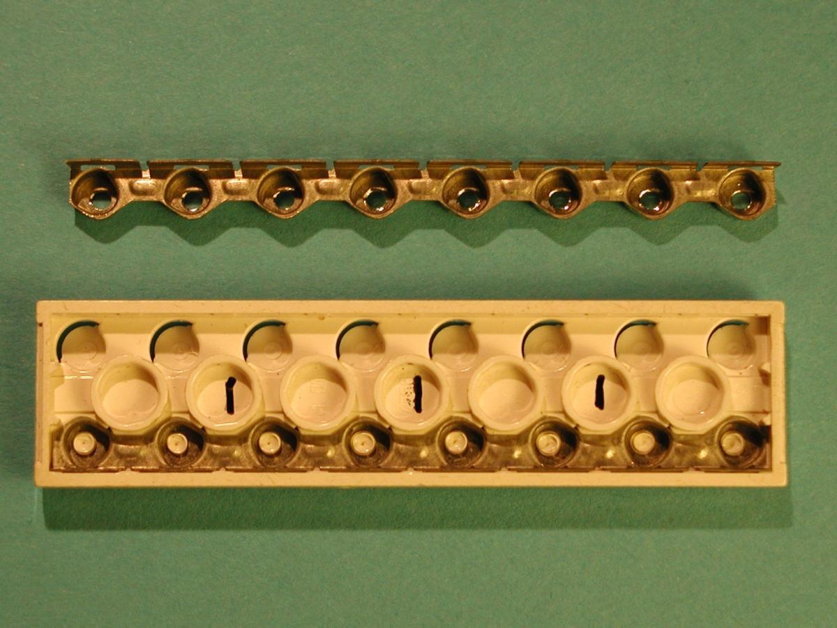 Step 3: Push the top strip out from the stud side (using a knife). Remove the remains of the welds (from stud side, with the knife). |
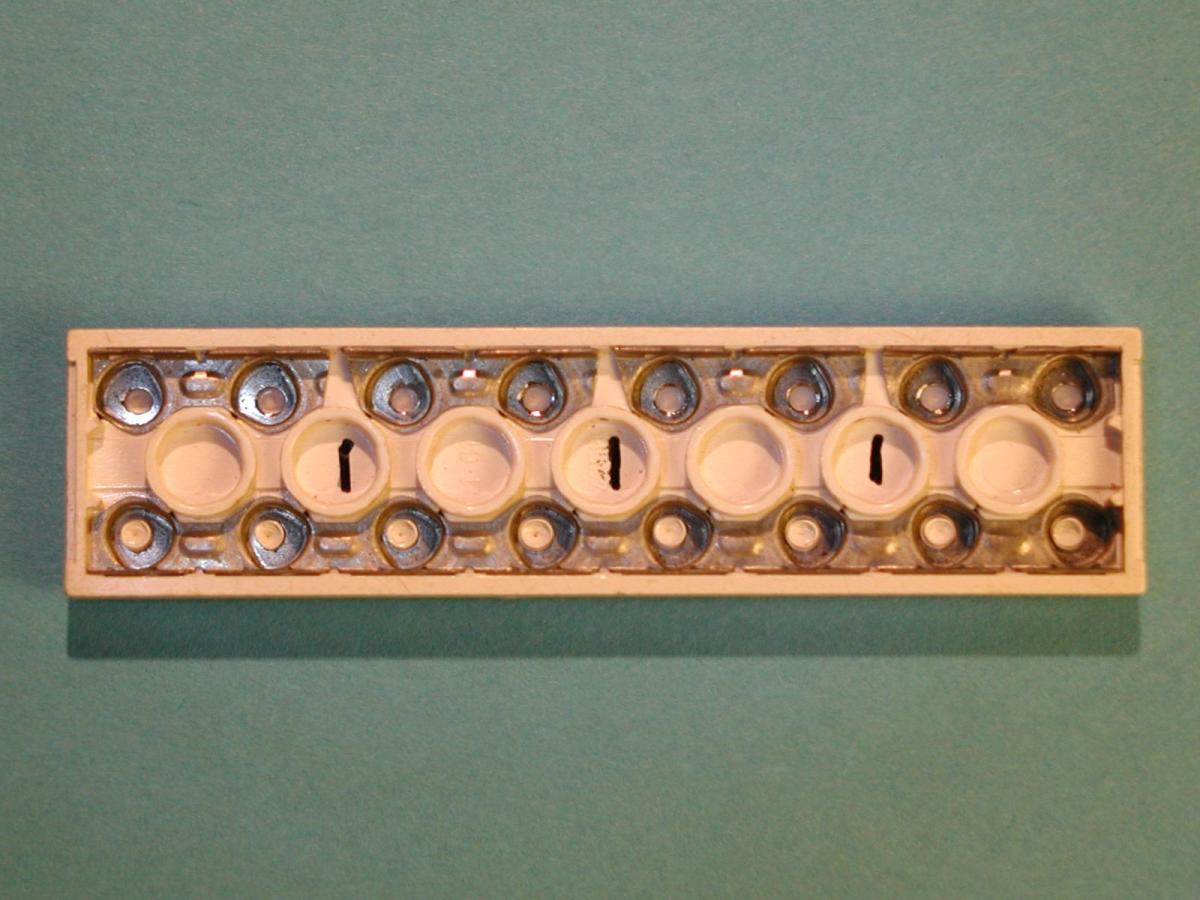
 Step 4: Cut the strip in four parts, each time remove metal from both sides, e.g. with a file. |
 Step 5: Use (not too much) super glue to fix the metal parts back in their original places. |
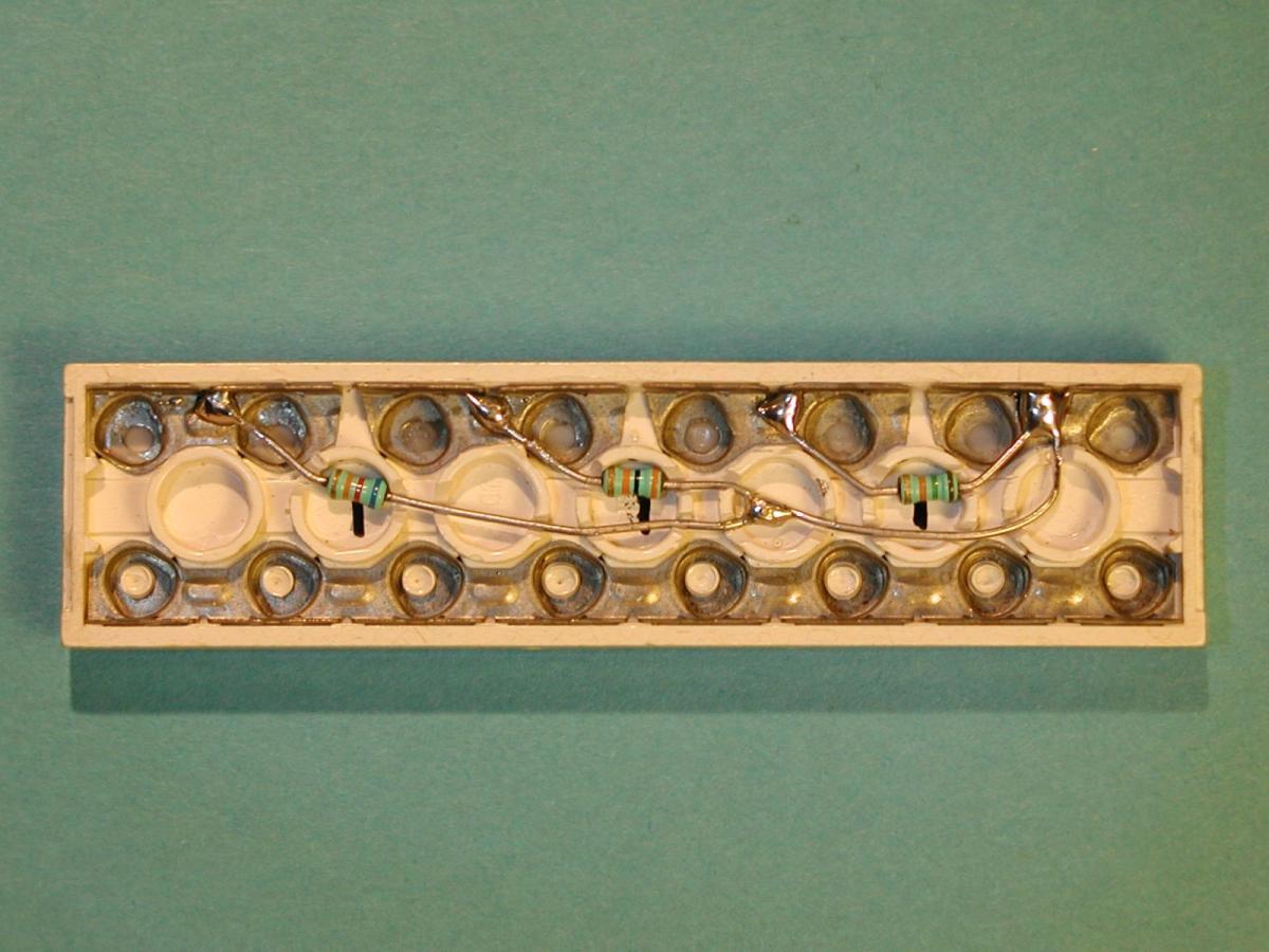 Step 6: Cut "canals" for the resistor wires. Solder small resistors, quickly (or the lego will melt). |
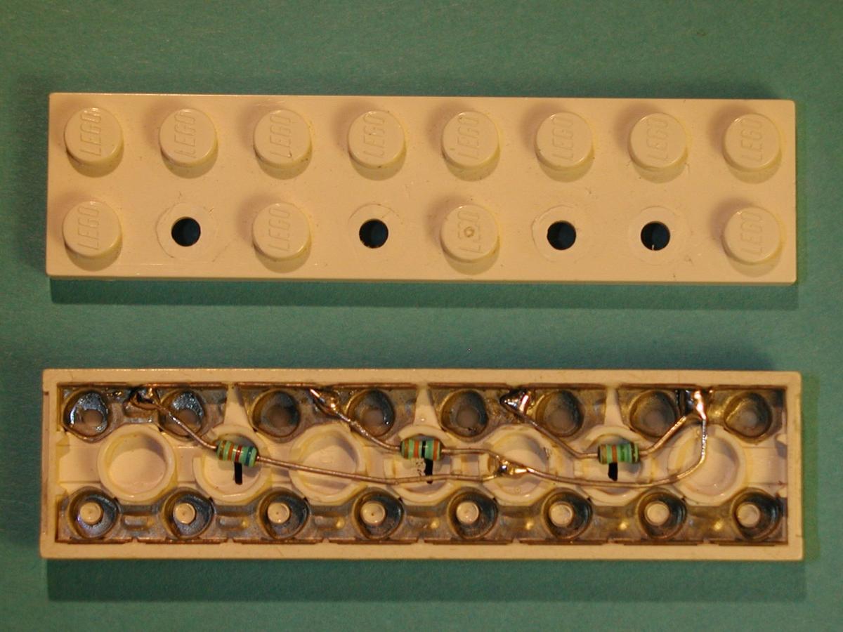 Step 7: Take a plain plate, and cut the studs (using a knife) where wires run. |
 Step 8: Glue the electric plate and the plain plate together with some drops of super glue. Add labels. We're done! |
| Manufacturing the multiplxer in 8 steps (click to enlarge) | |||

